The changes in refractive index can be implemented not only locally in a single point, but also during line scanning. This procedure can be applied durring normal AFM scanning while the femtpsecond laser is focused permanently onto the probe’s tip. The alignment need to be adjusted before begining the scanning. Depending on the preferences, different types of 2D waveguides can be designed and created in this way by adusting the number of scanning line, the scanning rate and the scanning points (digital resolution). The last two parameters are linked to the exposure time.
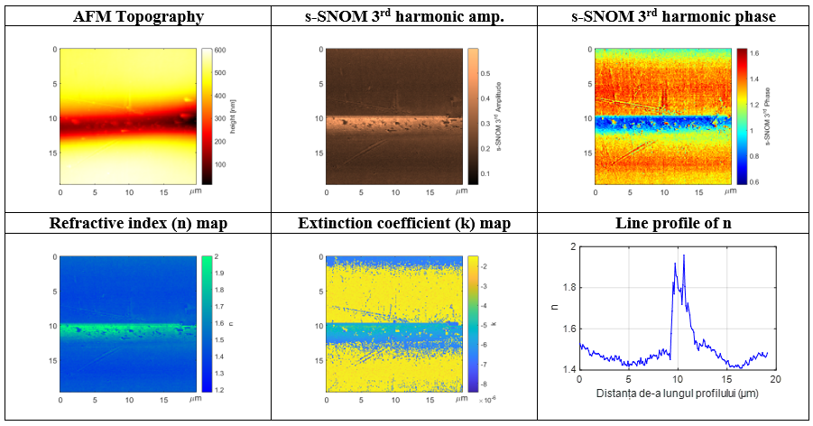
Here is an example of a multimode 2D waveguide imaged by AFM and s-SNOM. Refractive index and extinction coefficient maps are also displayed together with a transversal profile line along the “n” map of the waveguide.
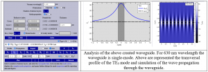
The designed waveguide was also analyzed using the PlasS program, which returned the following results:
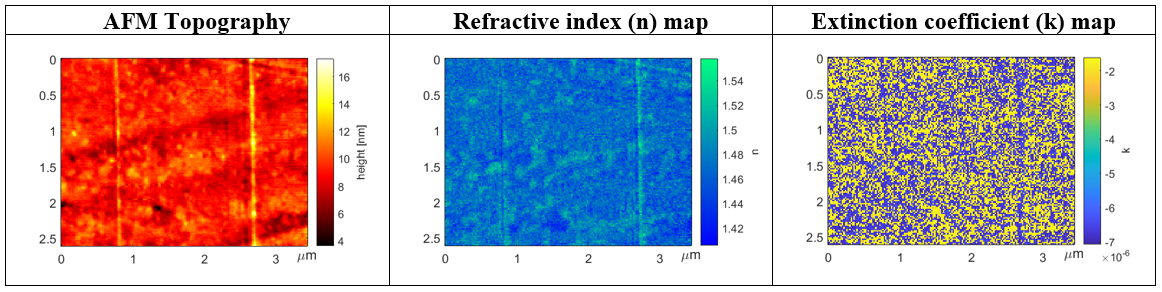
Another designed and implemented waveguide was a singlemode waveguide in which a small number of scanning line was choosen. In this way the transversal size (diameter) of the waveguide will be smaller. The result was investigated by AFM and s-SNOM:
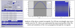
Again, the above designed waveguide was analyzed using the PlasS program, which returned the following results: